Infrared thermography is the process of using a thermal imager to detect radiation from an object. Below, we’ll discuss how infrared thermography works and how we use it in preventive maintenance.

What Is Infrared Thermography?
Infrared thermography is the process of using a thermal imager to detect radiation (heat) coming from an object, converting it to temperature and displaying an image of the temperature distribution. Images of the detected temperature distribution are called thermograms, and they make it possible to see heat-producing objects invisible to the naked eye. It’s widley-used in predictive maintenance and condition monitoring.
Since all objects above absolute zero (-459.67 degrees Fahrenheit) give off thermal infrared energy, thermal imagers can easily detect and display infrared wavelengths regardless of ambient light. A common example of this is using night-vision goggles to detect objects in the dark.
Infrared thermography is commonly used in a variety of industries and applications including:
- Electrical system monitoring
- Fluid system monitoring
- Machine condition monitoring
- Chemical imaging
- Earth science imaging
- Building diagnostics like moisture, roof and energy-loss inspections
Specific to plant maintenance and condition monitoring, infrared thermography is used in applications such as:
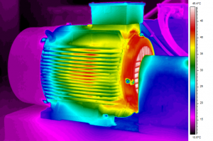
- Monitoring the electrical and mechanical conditions of a motor
- Bearing inspections (abnormal bearing friction)
- Monitoring refractory insulation
- Locating gas, liquids and sludge levels
The primary goal of infrared thermography is to confirm machinery is running normally and to detect abnormal heat patterns within a machine, indicating inefficiency and defects. Inspecting mechanical equipment using infrared thermography is a big advantage for asset managers tasked with condition monitoring. Even though infrared imagers are simple to use, interpreting the data they produce can be a bit more challenging to break down. It’s important not only to have a working knowledge of how infrared imagers work, but also baseline knowledge of radiometry and heat transfer processes.
Types of Infrared Thermometers we use.
An infrared thermometer in its most basic form consists of a lens that focuses the infrared thermal radiation onto a detector, which turns the radiant energy into a color-coded signal. Infrared thermometers are designed to measure temperature from a distance, preventing the need for contact with the object being measured. Today, there are a variety of infrared thermometer configurations for specific applications. Following is a look at three of the different types we use.
- Spot infrared thermometers: Also known as a pyrometer, a spot infrared thermometer resembles a handheld radar gun and is used to detect and measure the temperature at a specific spot on a surface. Spot infrared thermometers are ideal for measuring thermal radiation on hard-to-reach assets or assets operating under extreme conditions.

You may have seen heating, ventilation and air conditioning (HVAC) technicians using a spot infrared thermometer by pointing the gun toward the ceiling vents to check the temperature of a ventilation system in your office building or home. Common applications for using a spot infrared thermometer for preventive maintenance include:
- Checking bearings and belts
- Monitoring electrical rooms
- Energy audits looking for heat loss
- Fluid-handling systems
- Water leaks
- Panel boards
- Rotating motor monitoring
- Boiler operations and steam system monitoring
Spot infrared thermometers work by using field of view (FOV) and distance-to-spot ratio (D:S). When measuring the temperature of an asset with a spot thermometer, make sure the target is completely in the thermometer’s FOV. Also, consider the distance-to-spot ratio, as an error can occur if the background temperature varies from the target temperature. The distance-to-spot ratio is the ratio of the distance to the object you’re measuring and the diameter of the temperature measurement area. The larger the ratio number, the better the instrument’s resolution and the smaller the area that can be measured. For example, a spot thermometer with a 40-to-1 ratio more accurately measures a smaller object than one with a 10-to-1 ratio.
- Infrared scanner systems: We use these infrared thermometers as they can scan a larger area and we often use them in manufacturing plants with electric and fluid applications of machine and plant process.
A thermal-imaging camera is an advanced type of radiation thermometer used for measuring temperature at multiple points across a large area and creating two-dimensional thermographic images. Thermal-imaging cameras are considerably more software- and hardware-based than a spot thermometer. Most cameras display real-time images and can be hooked up to specialized software for deeper evaluation, accuracy and report generation. Modern thermal-imaging cameras are handheld.Infrared thermal-imaging cameras let users toggle between multiple color palettes to help decipher various temperature differences.
-
- Iron palette: The iron palette is the most common. It shows the coldest areas in black, slightly hotter areas in blue/purple, mid-range temperatures in red/orange/yellow and white for the hottest temperatures.
- Black and white palette: Sometimes called grayscale, this color palette displays details very well by only showing black to white colors passing through multiple levels of gray. The most common application for grayscale is night vision or security cameras. It’s rarely used in machinery imaging because it’s more difficult to distinguish temperature variation when only two colors are used.
- Rainbow palette: The rainbow palette shows thermal sensitivity the best by displaying temperature differences through multiple colors. Similar to the iron palette, the rainbow palette uses more color to indicate greater temperature variation.
Other infrared camera features include a color alarm, picture-in-picture and fusion blending. The color alarm lets you select a temperature, so the camera will only show a color thermal image of an asset below or above the selected temperature. Fusion blending allows you to blend the minimum or maximum average temperature of a thermal image with a standard digital image.
It’s easy to get distracted with the features of a thermal-imaging camera, and many of those features offer valuable information. So, what should you look for in a thermal-imaging camera? The two most important features you should consider are the detector resolution and thermal sensitivity.
- Detector resolution: Detector resolution tells you the number of pixels displayed in your images. Your camera should include the most common resolutions of 160×120, 320×240 and 640×480. A 640×480 imager displays an image made up of 307,200 pixels.
- Thermal sensitivity: This refers to the smallest temperature difference the thermal-imaging camera can detect. For example, a camera showing a sensitivity of 0.05 degrees means it can tell the difference between two surfaces with a five-hundredth of a degree temperature difference.
Also, consider the thermal-imaging camera’s temperature range, which is the minimum and maximum temperature the camera can measure. The typical temperature range is minus 4 degrees Fahrenheit to 2,200 degrees Fahrenheit.
Common applications for using a inferred scanner for preventive maintenance include:
How we use Infrared Thermography
Infrared thermography is a valuable tool for condition monitoring and preventive maintenance. Not only does it allow us to detect thermal abnormalities of machines, but it lets us do so in a non-intrusive, hands-off way while still getting results in real-time. We employ one of three methods when performing thermal inspections: comparative, baseline and thermal trending. Determining which method to use comes down to the type of equipment we are testing and the type of data our clients want to see.
- Comparative thermography: Comparative thermography is used to measure the temperature of similar components under similar conditions. By comparing the results, useful information about the components’ condition is obtained, thanks to the uncovering of hidden problems. Comparative thermography comparisons can be quantitative or qualitative. Quantitative inspections measure precise temperature and/or temperature distribution and are typically performed by a highly trained thermographer.Qualitative inspections focus on the differences in temperature rather than actual temperatures. Nearly all (90 percent) industrial and mechanical applications for modern thermography are qualitative, but using quantitative measurements in tandem with qualitative measurements can help determine the severity of the condition as well as the problem itself.
- Baseline thermography: Baseline thermography is used to set a precedent or establish a reference point for an asset by taking temperature readings when the asset is in good working order. It is used in comparison with other thermal images to identify potential issues early. It’s recommended to take baseline measurements on all critical assets when they are new or have just been repaired.
- Thermal-trending thermography: Just as trends show changes over time, thermal-trending thermography shows how temperature is dispersed in a component or asset over time. It’s a great method for looking at mechanical equipment with complex thermal signatures or when thermal signatures develop slowly. A great example of using thermal trending is monitoring high-temperature refractory insulation in a boiler over time to help determine a proper maintenance schedule that minimizes downtime.
Infrared Thermography Assessment Criteria
When using infrared thermography as a tool for condition monitoring, it’s recommended we establish severity criteria. Severity criteria can be presented in two forms: general categories identifying temperature levels or specific categories of machines or components. Severity criteria develops over time with an accumulation of data. It’s best practice to develop severity criteria specific to each category of equipment based on the equipment’s design, operation, installation, maintenance characteristics, criticality and failure modes.
Establishing severity criteria on individual machines or components is based on a number of factors, including temperature rise vs. historical data, determining the rate of deterioration and time to failure, how critical the machine or component is to the overall process, safety, etc. Rises in temperature for critical machines, mechanical components, bearings, electrical supply and more are common applications used by thermographers to classify temperature severity or mechanical abnormalities.
- Relative temperature criteria: Relative temperature criteria are a set of safety criteria based on temperature rises divided into categories. For example, you may have advisory, intermediate, serious and critical categories. Under the advisory category, you may have a set rule stating that a machine falls under the advisory category when the temperature rises 10 degrees above a reference or baseline temperature. The critical category may state that a machine falls under the critical category when the temperature rises more than 104 degrees above a reference or baseline temperature.
- Absolute temperature criteria: We may use material or design criteria based on the absolute maximum allowable temperature derived from previously published data. Material criteria are used when the monitoring focus is on the machine’s material, while design criteria are used when the monitoring focus is on the machine’s design. Although the criteria is divided into these two categories, design usually encompasses the material aspect, which makes it the preferred criteria when it comes to monitoring reliability. If we are using material criteria to measure the heating of multiple adjacent components, the component material with the lowest temperature specification should be used as your “alarm criteria.”
- Profile assessment criteria: We compare temperature differences and patterns across any surface, we are practicing a process known as profile assessment. In the case of thermography, to perform a profile assessment, you must first conduct a severity assessment to determine the absolute and differential temperatures. This will tell us the condition of the machine or component based on two categories: “as new” or “failed.” The key areas of a profile assessment are temperature gradients, historical changes, localized differences, absolute temperatures or location of abnormalities, according to Hitchcock.

Infrared Thermography Testing Techniques
When it comes to infrared thermography testing techniques, there are several options from which we can choose. Our selection will depend on the considerations discussed above, including what set of data our clients need and what we are monitoring. Let’s take a look at some of the most common infrared thermography testing techniques.
- Passive thermography: This testing technique involves taking thermal images while the machine is running or immediately after operation. This allows you to gather data without an external energy source or taking the machine offline.
- Active thermography: This technique requires an external energy source to create temperature variances in the component which are influenced by interior materials and defects. It is used to show how heat flows through a component and for locating abnormalities in components while in use.
- Flash thermography: This technique uses pulses of light to locate gaps, inclusions or other obstructions that block heat flow into a component.
- Vibrothermography: By introducing acoustic waves into a machine or component, vibrothermography can determine where cracks may have formed in the material. The disturbance caused by acoustic energy creates friction between the two rough edges on either side of the crack. This produces heat, which is detected by the infrared camera.
- Lock-in thermography: Like many of the other techniques, lock-in thermography requires that an external energy source (light, sound, heat, etc.) be applied to a component’s surface to reveal abnormalities below the surface. It’s important to know the depth, size and location of the abnormality, as well as the material makeup and properties for this technique to be accurate. While it takes longer than the techniques previously discussed, it can penetrate components with thicker walls.
Infrared Thermography and Preventive Maintenance
Infrared thermography is a highly recommended preventive maintenance tool in nearly all industries. You won’t find another tool that gives you such accurate, real-time data without disrupting the process flow from shutting down your systems. Working infrared thermography into your regularly scheduled maintenance procedures is a great way to catch abnormalities in components and machines quickly. Using baseline thermography on new equipment or after repairing equipment will provide a set of thermal images to compare all other tests against and lets you more easily troubleshoot future issues.
Advantages vs. Disadvantages of Infrared thermography
Advantages of using infrared thermography in preventive maintenance include:
- Requires no contact with components or machines
- Real-time output
- Can obtain data on large surface areas at one time
- Easy-to-read visual images
- Data can be uploaded to software for further analysis
- Infrared cameras offer great mobility
- No downtime or production interruptions for testing
While there are many advantages to using infrared thermography, it’s always a good idea to be aware of some of the disadvantages:
- Infrared technology can’t detect temperature if a component is separated by a non-transparent material such as a glass cover. When viewed with an infrared imager, glass appears in a non-transparent way.